Replacement Cylinders
General Dimensions & Specifications
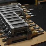
Fronek A/DE offers complete replacement cylinders that come factory preset to customer specifications. They are designed to mate to existing Fronek A/DE hardware and ship coated with a corrosion resistant primer. Alternate coatings can be furnished upon request.
Fronek A/DE can supply two types of cylinder conficurations. Type NF, the extended tie rod configuration, is furnished with a base end mounting arrangment consisting of extended main cylinder tie rods (Figure 1). This type of configuration is compatible with Fronek A/DE’s Fig 510 and Fig 511 hardware. Type M77, the flange mount configuration, is nearly identical to the Type NF except that the base end mounting arrangment consists of a separate flange (Figure 2). Both cylinder types can be furnished for either nuclear or commercial applications.
The part and model numbers provided in the tables below are applicable to "Nuclear" grade product. For ‘Commercial’ grade applications, the part number is increased by 40 and the model number is appended with the letter ‘C’. For example:
|
‘Nuclear’ |
P/N 60501, Model No. ADH-2000L |
|
coresponds to |
|
|
‘Commercial’ |
P/N 60541, Model No. ADH-2000LC |
When ordering, please specify model number, cylinder size, and stroke.
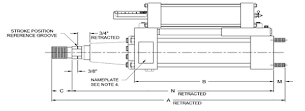
Figure 1 – Type NF, Extended Tie Rod Configuration
|
Kip Size |
Cylinder |
Assemblies with Non-Relief Valve |
N-Retracted |
||
|
Part No. 60XXX |
Model Number ADH-XXXXXX |
||||
|
Bore |
Stroke |
||||
|
3 |
1.5 |
6 |
330 |
303 |
16.0 |
|
3 |
1.5 |
12 |
331 |
303L |
22.0 |
|
3 |
1.5 |
18 |
332 |
303XL |
28.0 |
|
10 |
2.5 |
6 |
430 |
1003 |
16-1/2 |
|
10 |
2.5 |
12 |
431 |
1003L |
22-1/2 |
|
10 |
2.5 |
18 |
432 |
1003XL |
28-1/2 |
|
20 |
3.25 |
6 |
530 |
2003 |
17-3/8 |
|
20 |
3.25 |
12 |
531 |
2003L |
23-3/8 |
|
20 |
3.25 |
18 |
532 |
2003XL |
29-3/8 |
|
30 |
4.0 |
6 |
630 |
3003 |
17-3/4 |
|
30 |
4.0 |
12 |
631 |
3003L |
23-3/4 |
|
30 |
4.0 |
18 |
632 |
3003XL |
29-3/4 |
|
50 |
5.0 |
6 |
730 |
5003 |
18-1/4 |
|
50 |
5.0 |
12 |
731 |
5003L |
24-1/4 |
|
50 |
5.0 |
18 |
732 |
5003XL |
30-1/4 |
|
70 |
6.0 |
6 |
830 |
7003 |
19-1/2 |
|
70 |
6.0 |
12 |
831 |
7003L |
25-1/2 |
|
70 |
6.0 |
18 |
832 |
7003XL |
31-1/2 |
|
130 |
8.0 |
6 |
930 |
13003 |
21-3/16 |
|
130 |
8.0 |
12 |
931 |
13003L |
27-3/16 |
|
130 |
8.0 |
18 |
932 |
13003XL |
33-3/16 |
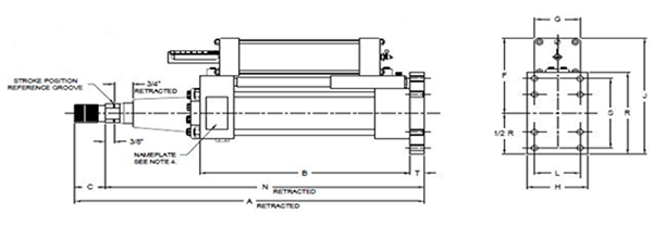
Figure 2 – Type M77, Flange Mount Configuration
|
Kip Size |
Cylinder |
Assemblies with Non-Relief Valve |
N-Retracted |
L |
S |
||
|
Part No. 60XXX |
Model Number ADH-XXXXXX |
||||||
|
Bore |
Stroke |
||||||
|
3 |
1.5 |
6 |
310 |
301 |
16-1/2 |
1.63 |
3.43 |
|
3 |
1.5 |
12 |
311 |
301L |
22-1/2 |
1.63 |
3.43 |
|
3 |
1.5 |
18 |
312 |
301XL |
28-1/2 |
1.63 |
3.43 |
|
10 |
2.5 |
6 |
410 |
1001 |
17-1/8 |
2.55 |
4.62 |
|
10 |
2.5 |
12 |
411 |
1001L |
23-1/8 |
2.55 |
4.62 |
|
10 |
2.5 |
18 |
412 |
1001XL |
29-1/8 |
2.55 |
4.62 |
|
20 |
3.25 |
6 |
510 |
2001 |
18-1/8 |
3.25 |
5.88 |
|
20 |
3.25 |
12 |
511 |
2001L |
24-1/8 |
3.25 |
5.88 |
|
20 |
3.25 |
18 |
512 |
2001XL |
30-1/8 |
3.25 |
5.88 |
|
30 |
4.0 |
6 |
610 |
3001 |
18-5/8 |
3.82 |
6.37 |
|
30 |
4.0 |
12 |
611 |
3001L |
24-5/8 |
3.82 |
6.37 |
|
30 |
4.0 |
18 |
612 |
3001XL |
30-5/8 |
3.82 |
6.37 |
|
50 |
5.0 |
6 |
710 |
5001 |
19-1/8 |
4.95 |
8.18 |
|
50 |
5.0 |
12 |
711 |
5001L |
25-1/8 |
4.95 |
8.18 |
|
50 |
5.0 |
18 |
712 |
5001XL |
31-1/8 |
4.95 |
8.18 |
|
70 |
6.0 |
6 |
810 |
7001 |
20-1/2 |
5.73 |
9.43 |
|
70 |
6.0 |
12 |
811 |
7001L |
26-1/2 |
5.73 |
9.43 |
|
70 |
6.0 |
18 |
812 |
7001XL |
32-1/2 |
5.73 |
9.43 |
|
130 |
8.0 |
6 |
910 |
13001 |
22-5/8 |
7.37 |
12.12 |
|
130 |
8.0 |
12 |
911 |
13001L |
28-5/8 |
7.37 |
12.12 |
|
130 |
8.0 |
18 |
912 |
13001XL |
34-5/8 |
7.37 |
12.12 |
Applications & Industries Served
Ammonia Plant
Chemical Plant
Clean Fuels
Commercial
Chemical Plant
Clean Fuels
Commercial
Electric Plant
Energy Facility
Ethylene Plant
LLDPE Chemical Plant
Energy Facility
Ethylene Plant
LLDPE Chemical Plant
LNG Plant
MTBE Plant
Natural Gas Combined Cycle Facility
Natural Gas Processing & Separation
MTBE Plant
Natural Gas Combined Cycle Facility
Natural Gas Processing & Separation
Oil Refinery
Oil Sand Mine
Paper Manufacturer
Oil Sand Mine
Paper Manufacturer
Photo Gallery