Fig 510/511
General Dimensions & Specifications
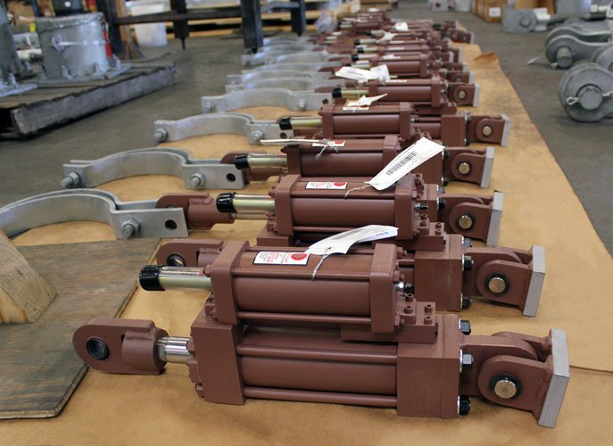
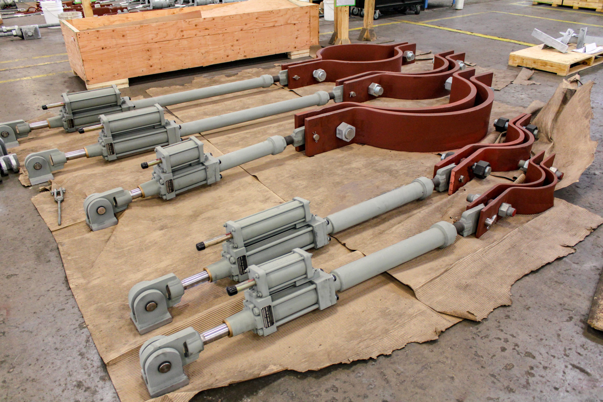
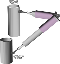
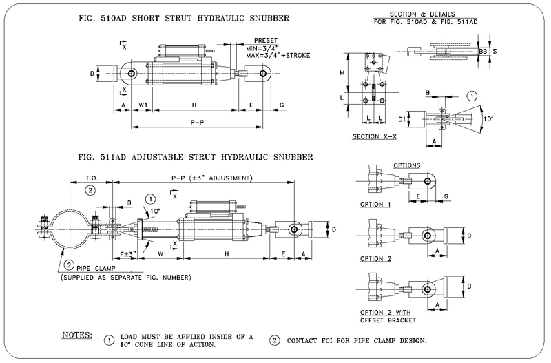
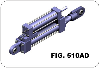
Fig 510AD Short Strut Hydraulic Snubbers
 |
  |
ORDERING: Specify figure number, description, cylinder size, stroke, load, thermal movement, overall length, and piston end option. If a pipe clamp is required, please specify nominal pipe size or special O.D., pipe temperature, and any additional option features (i.e. integral relief valve or remote reservoir mounting) or special settings required.
Fig. 510AD – SHORT STRUT HYDRAULIC SNUBBER
| Cylinder | Approx. Weight (1) | H Min. (2) |
P-P Min. (2) | Load Rating (KIPS) | A | B | D | D1 | E | G | L | M | W1 | S | BB | |
| Size | Stroke | |||||||||||||||
| 1 1/2 | 6 | 35 | 16 | 21 | 3 | 2 | 3/4 | 2 1/2 | 2 3/4 | 3 | 1 1/16 | 1 1/4 | 5 | 2 | 3/4 | 0.656 |
| 12 | 42 | 22 | 27 | |||||||||||||
| 18 | 50 | 28 | 33 | |||||||||||||
| 2 1/2 | 6 | 70 | 16 1/2 | 23 1/4 | 10 | 2 1/2 | 1 | 3 | 3 1/2 | 3 3/4 | 1 1/2 | 1 3/4 | 6 | 3 | 1 | 0.875 |
| 12 | 83 | 22 1/2 | 29 1/4 | |||||||||||||
| 18 | 96 | 28 1/2 | 35 1/4 | |||||||||||||
| 3 1/4 | 6 | 125 | 17 3/8 | 27 1/8 | 20 | 4 | 1 1/2 | 5 | 4 3/4 | 5 1/2 | 2 1/2 | 2 1/4 | 7 3/8 | 4 1/4 | 1 1/2 | 1.312 |
| 12 | 145 | 23 3/8 | 33 1/8 | |||||||||||||
| 18 | 165 | 29 3/8 | 39 1/8 | |||||||||||||
| 4 | 6 | 155 | 17 3/4 | 28 1/2 | 30 | 4 | 1 1/2 | 5 | 4 3/4 | 6 1/2 | 2 1/2 | 2 1/2 | 8 1/2 | 4 1/4 | 1 1/2 | 1.312 |
| 12 | 180 | 23 3/4 | 34 1/2 | |||||||||||||
| 18 | 205 | 29 3/4 | 40 1/2 | |||||||||||||
| 5 | 6 | 255 | 18 1/4 | 31 3/4 | 50 | 5 1/2 | 2 | 7 | 6 | 8 | 3 1/2 | 3 1/4 | 10 1/4 | 5 1/2 | 1 7/8 | 1.75 |
| 12 | 290 | 24 1/4 | 37 3/4 | |||||||||||||
| 18 | 325 | 30 1/4 | 43 3/4 | |||||||||||||
| 6 | 6 | 410 | 19 1/2 | 33 3/4 | 70 | 6 | 2 1/4 | 7 | 6 1/2 | 8 1/2 | 4 | 3 3/4 | 11 7/8 | 5 3/4 | 2 1/4 | 1.968 |
| 12 | 465 | 25 1/2 | 39 3/4 | |||||||||||||
| 18 | 520 | 31 1/2 | 45 3/4 | |||||||||||||
| 8 | 6 | 805 | 21 3/16 | 41 7/16 | 130 | 8 1/2 | 3 | 10 | 10 | 12 1/2 | 5 1/2 | 4 3/4 | 16 | 7 3/4 | 2 7/8 | 2.625 |
| 12 | 890 | 27 3/16 | 47 7/16 | |||||||||||||
| 18 | 975 | 33 3/16 | 53 7/16 | |||||||||||||
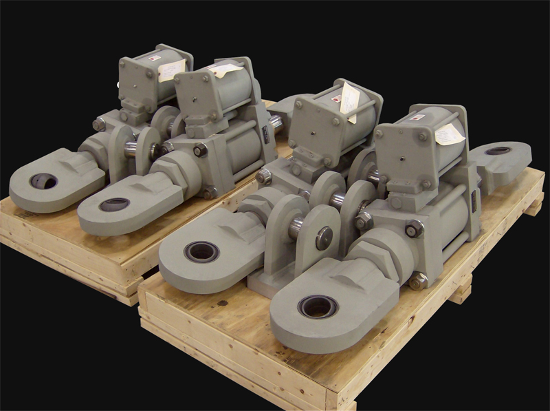
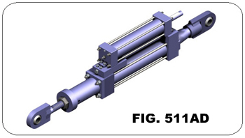
Fig. 511AD – ADJUSTABLE STRUT HYDRAULIC SNUBBER
| CYLINDER | APPROX. WEIGHT (1) | P-P | F | W MIN. | ||
| SIZE | STROKE | MIN. | (4) MAX. | |||
| 1 1/2 | 6 | 40 | 32 3/4 | 100 | 6 1/4 | 7 1/2 |
| 12 | 47 | 38 3/4 | 100 | |||
| 18 | 54 | 44 3/4 | 100 | |||
| 2 1/2 | 6 | 75 | 36 1/4 | 120 | 7 1/4 | 8 3/4 |
| 12 | 90 | 42 1/4 | 120 | |||
| 18 | 105 | 48 1/4 | 120 | |||
| 3 1/4 | 6 | 130 | 41 5/8 | 120 | 9 1/2 | 9 1/4 |
| 12 | 150 | 47 5/8 | 120 | |||
| 18 | 170 | 53 5/8 | 120 | |||
| 4 | 6 | 200 | 44 1/8 | 120 | 10 1/8 | 9 3/4 |
| 12 | 225 | 50 1/8 | 120 | |||
| 18 | 250 | 56 1/8 | 120 | |||
| 5 | 6 | 330 | 49 1/2 | 120 | 12 1/2 | 10 3/4 |
| 12 | 365 | 55 1/2 | 120 | |||
| 18 | 400 | 61 1/2 | 120 | |||
| 6 | 6 | 530 | 53 3/8 | 120 | 13 3/4 | 11 5/8 |
| 12 | 590 | 59 3/8 | 120 | |||
| 18 | 645 | 65 3/8 | 120 | |||
| 8 | 6 | 1050 | 62 11/16 | 120 | 16 1/4 | 13 3/8 |
| 12 | 1140 | 68 11/16 | 120 | |||
| 18 | 1225 | 74 11/16 | 120 | |||
| Fig. 510AD & 511AD: Dimensions | ||||
| CYLINDER SIZE | A | Fig. 510AD P-P Retracted1 | Fig. 511AD P-P Retracted1 | MAX.RECOM. NORMAL LOAD2 (lb.) |
| 1 1/2 | 2 | 21 | 32 3/4 | 3,000 |
| 2 1/2 | 2 1/2 | 23 1/4 | 36 1/4 | 10,000 |
| 3 1/4 | 4 | 27 1/8 | 41 5/8 | 20,000 |
| 4 | 4 | 28 1/2 | 44 1/8 | 30,000 |
| 5 | 5 1/2 | 31 3/4 | 49 1/2 | 50,000 |
| 6 | 6 | 33 3/4 | 53 3/8 | 70,000 |
| 8 | 8 1/2 | 41 7/16 | 62 11/16 | 130,000 |
| 1Add cold piston setting for install length. These values reflect cylinders having 6″ of stroke. 2Load must not be applied utisde 10º included angle cone of action to the pipe clamp axis w/o special authorization. |
||||
|---|---|---|---|---|
Applications & Industries Served
Ammonia Plant
Chemical Plant
Clean Fuels
Commercial
Chemical Plant
Clean Fuels
Commercial
Electric Plant
Energy Facility
Ethylene Plant
LLDPE Chemical Plant
Energy Facility
Ethylene Plant
LLDPE Chemical Plant
LNG Plant
MTBE Plant
Natural Gas Combined Cycle Facility
Natural Gas Processing & Separation
MTBE Plant
Natural Gas Combined Cycle Facility
Natural Gas Processing & Separation
Oil Refinery
Oil Sand Mine
Paper Manufacturer
Oil Sand Mine
Paper Manufacturer
Photo Gallery