Hydraulic Snubbers Guide
The style “AD” Hydraulic Shock Arrestor is a manifold design hydraulic component consisting of a high pressure main cylinder, a flow control section which contains dual stage velocity sensitive poppet valves, and a spring energize reservoir.
Application:
For use on piping systems or equipment when unrestrained thermal movement must be allowed, but which must be restrained during impulsive or cyclic disturbance. The unit is not effective against low amplitude, high frequency movement. The preferred usage with standard settings is to prevent destructive results due to earthquakes, flow transients, or wind load. Special settings are available to absorb the continuous thrust resulting from safety valve blow-off or pipe rupture.
Size Range:
PTP offers seven sizes with cylinder bores of 1 1/2 to 8 inches. These units have a normal load range of 3,000 lbs. to 130,000 lbs. All are made to include reservoirs in 6, 12, or 18 inch strokes, except the 1 1/2 inch size. The 1 1/2 inch size is offered only in 6 & 12 inch strokes only. Snubbers, as they are sometimes referred to, are available with remote reservoirs.
Size Selection:
The selection of size depends on the anticipated force and thermal movement of the protected piping or equipment. It is recommended that the selected cylinder stroke be a minimum of the anticipated thermal movement, plus 20%.
Basic Operation:
The piston rod is free to move in either direction with no restrictions to the fluid flow for all piston velocities up to the activation velocity. At activation velocity the poppet valve, internal to the snubber, closes. Closure of the poppet in either tension or compression greatly reduces the fluid flow through grooves in the poppet at rated design capacity of the unit is termed the “ bleed rate”. When the applied velocity of the unit becomes zero the poppet valve opens once again, allowing free piston movement.
Standard Design Features:
– Piping and/or equipment movement is controlled by tamperproof dual stage flow control poppets designed with self-cleaning orifices.
– Furnished as a complete, compact and efficient unit, ready for immediate use.
– Manifold configuration requiring no external piping.
– Spherical, self-aligning ball bushings allow for ±5º of angular motion or misalignment.
– Stable premium grade, antiwear hydraulic fluid.
– Pressurized hydraulic reservoir allows mounting in any spatial orientation.
– Virtually no resistance to normal thermal movements of the piping.
– Large restraining forces compared to size.
– Functions in restraining tension and compression loads.
– Designed for continuous operation up to 200°F with brief transients to a maximum of 300°F.
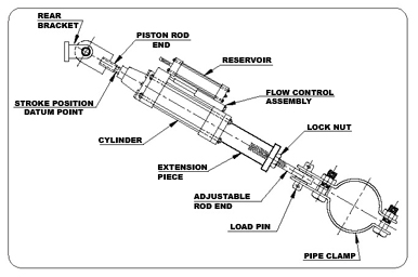
– Stroke position is measured from a machined groove located at the piston rod wrench flats.
– Fluid Level in the unit, thereby eliminating estimate of reserve fluid level.
Optional Design Features:
– Remote Reservoir Mounting
– The snubber’s pressurized reservoir can be remotely mounted for inaccessible locations.
– Integral Relief Valve- A non-adjustable valve, which is factory preset at 133%, or 200% of rated load.
– Protective Boot- Installed over piston rod for protection against corrosive or outdoor environments.
– Rigid Stud Application- When no thermal growth is anticipated after lock-up, an optional poppet valve, without bleed, can be furnished. Must be ordered with optional integral relief valve.
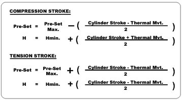
Factory Pre-set:
The units are shipped from the factory complete, tested, reservoir filled to capacity and piston rod preset to mate with pin to pin installation dimension. To determine factory pre-set dimension perform the following calculations.
Most hydraulic snubbers have a piston which is relatively unconstrained in motion at low displacement rates. At high displacement rates the piston “locks up”, that is, the force required to move the piston increases substantially, usually as a result of the closing of a valve.
Some of the features include:
– External pressurized hydraulic reservoir for positioning flexibility in any spatial orientation.
– Allows free thermal movement of piping under normal operations.
– Restrains shock loading, both in tension and compression.
– System’s movement is controlled by a flow control device.