Hydraulic Snubbers Guide

Hydraulic Snubbers Guide

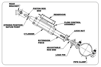
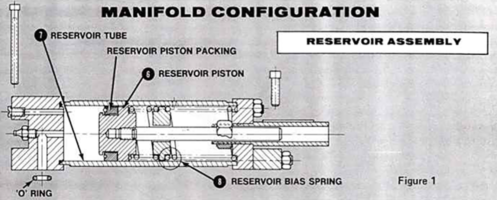
The style “AD” Hydraulic Shock Arrestor is a manifold design hydraulic component consisting of a high pressure main cylinder, a flow control section which contains dual stage velocity sensitive poppet valves, and a spring energize reservoir.

Fig510ad 511ad snubber 2

Application:
For use on piping systems or equipment when unrestrained thermal movement must be allowed, but which must be restrained during impulsive or cyclic disturbance. The unit is not effective against low amplitude, high frequency movement. The preferred usage with standard settings is to prevent destructive results due to earthquakes, flow transients, or wind load. Special settings are available to absorb the continuous thrust resulting from safety valve blow-off or pipe rupture.

Size Range:
PTP offers seven sizes with cylinder bores of 1 1/2 to 8 inches. These units have a normal load range of 3,000 lbs. to 130,000 lbs. All are made to include reservoirs in 6, 12, or 18 inch strokes, except the 1 1/2 inch size. The 1 1/2 inch size is offered only in 6 & 12 inch strokes only. Snubbers, as they are sometimes referred to, are available with remote reservoirs.

Size Selection:
The selection of size depends on the anticipated force and thermal movement of the protected piping or equipment. It is recommended that the selected cylinder stroke be a minimum of the anticipated thermal movement, plus 20%.

Basic Operation:
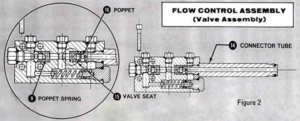
The piston rod is free to move in either direction with no restrictions to the fluid flow for all piston velocities up to the activation velocity. At activation velocity the poppet valve, internal to the snubber, closes. Closure of the poppet in either tension or compression greatly reduces the fluid flow through grooves in the poppet at rated design capacity of the unit is termed the “ bleed rate”. When the applied velocity of the unit becomes zero the poppet valve opens once again, allowing free piston movement.

Standard Design Features:
– Piping and/or equipment movement is controlled by tamperproof dual stage flow control poppets designed with self-cleaning orifices.
– Furnished as a complete, compact and efficient unit, ready for immediate use.
– Manifold configuration requiring no external piping.
– Spherical, self-aligning ball bushings allow for ±5º of angular motion or misalignment.
– Stable premium grade, antiwear hydraulic fluid.
– Pressurized hydraulic reservoir allows mounting in any spatial orientation.
– Virtually no resistance to normal thermal movements of the piping.
– Large restraining forces compared to size.
– Functions in restraining tension and compression loads.
– Designed for continuous operation up to 200°F with brief transients to a maximum of 300°F.
– Stroke position is measured from a machined groove located at the piston rod wrench flats.
– Fluid Level in the unit, thereby eliminating estimate of reserve fluid level.

Optional Design Features:
– Remote Reservoir Mounting
– The snubber’s pressurized reservoir can be remotely mounted for inaccessible locations.
– Integral Relief Valve- A non-adjustable valve, which is factory preset at 133%, or 200% of rated load.
– Protective Boot- Installed over piston rod for protection against corrosive or outdoor environments.
– Rigid Stud Application- When no thermal growth is anticipated after lock-up, an optional poppet valve, without bleed, can be furnished. Must be ordered with optional integral relief valve.

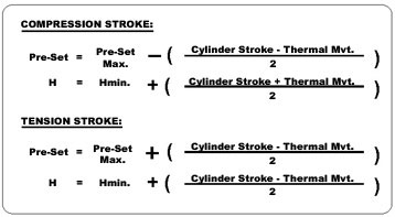
Hydraulic Snubber Equation

Factory Pre-set:
The units are shipped from the factory complete, tested, reservoir filled to capacity and piston rod preset to mate with pin to pin installation dimension. To determine factory pre-set dimension perform the following calculations.

Most hydraulic snubbers have a piston which is relatively unconstrained in motion at low displacement rates. At high displacement rates the piston “locks up”, that is, the force required to move the piston increases substantially, usually as a result of the closing of a valve.

Some of the features include:

– External pressurized hydraulic reservoir for positioning flexibility in any spatial orientation.
– Allows free thermal movement of piping under normal operations.
– Restrains shock loading, both in tension and compression.
– System’s movement is controlled by a flow control device.

Hydraulic Shock and Sway Arrestor GE SF 1154 Silicone Fluid

Bergen-Paterson HSSA NF Hydraulic Arrestors are supplied with General Electric SF 1154 fluid to meet all snubber applications. SF 1154 methly phenyl polysiloxane silicone fluid is a clear, light straw colored liquid, which possesses even better heat stability than the dimethyl polysiloxane (SF96-XXX) silicone materials which were previously supplied as the standard fluids in non-radiation applications. SF 1154 has outstanding heat resistance which is combined with low volatility and high flash point to provide a normal useful service temperature range of -40°F to +500°F. In addition, SF 1154 has excellent high temperature heat transfer characteristics which minimize localized heat spot- ting sources and aid energy dissipation during cyclic loading conditions.

The SF 1154 silicone fluid working in conjunction with unique chemical conversion dry film lubricants forms a lubrication system in the Hydraulic Arrestor which minimizes wear and prolongs service life. This system helps reduce the high break-in wear associated with new equipment and sets up the dual-seal cast iron piston rings as an excellent high pressure metallic seal.

The high energy (heat or radiation) resistance of the fluid is a result of the chemical structure of the silicone oxygen molecule. Where organic hydrocarbons fluids are based on a backbone of carbon-to-carbon atoms, the silicone fluid has a backbone of silicone-oxygen linkages similar to the Si-0 linkages in other high temperature materials (quartz, glass and sand). It is this Si-0 linkage that contributes to the outstanding broad-temperature characteristics and general inertness of the silicone fluid.


Some of the outstanding properties of the silicone fluid are:

  1. Low Viscosity Temperature Change –
    All fluids change viscosity with temperature change but GE SF 1154 silicone fluid exhibits a much smaller change than non silicone fluids.
  2. Wide Temperature Range –
    SF 1154 has a useful range of -40° to 500° F. which far surpasses conventional fluids.
  3. Excellent Thermal Stability-
    SF 1154 has shown excellent stability when exposed to very high temperatures.
  4. Excellent Oxidation Stability –
    Due to the absence of copper-induced oxidation, the sludging that normally occurs with mineral oils, especially at high temperatures, is eliminated. No evidence of sludging has been reported in service.


  1. Chemical Inertness –
    SF 1154 fluid is chemically inert to most common materials.
  2. Non-Flammability-
    SF 1154 is self-extinguishing. The flash point is in excess of 550°F, along with a fire point exceeding 650°F and an auto ignition temperature in the range of 880°F to 900°F.
  3. Excellent Shear Stability –
    Silicone fluids have unusually high resistance to breakdown by mechanical shearing. The shear sta- bility of silicone fluids can be as much as 20 times that of quality petroleum oils, providing long life. SF 1154 normally does not require change during the design life of the Arrestor.
  4. Excellent Heat Conductivity –
    The thermal conductivity of SF 1154 is relatively constant over its wide temperature range, making it ideal as a working fluid for Hydraulic Arrestors.
  5. Non-Corrosive-
    GE SF 1154 contains no acid producing chemicals to cause staining or corrosion.


  1. Radiation Resistance –
    GE SF 1154 is rated serviceable at 1 X 10⁸ roentgens which far exceeds normal nuclear plant design radia- tion levels.


TYPICAL PROPERTIES* of SF 1154 SILICONE FLUID


1. Nominal Viscosity @ 77°F 175 190 centistokes
2. Viscosity Temperature Coefficient .78
3. Specific Gravity @77°F 1.050
4. Pour Point -40°F
5. Flash Point >550°F
6. Fire Point >650°F
7. Auto Ignition Temperature 880°F 900°F
8. Specific Heat BTU/lb/°F .39
9. Radiation Resistance 1 X 10⁸ Roentgens Min.
10. Toxicity Low to None
11. Storage Life Indefinite
12. Bulk Modulus @ 100° F 245,000 psi


*The properties listed are typical and should not be used as specification limits. Specific details and test properties may be obtained from the General Electric Company, Waterford, New York.


Due to the inertness and stability of SF 1154 fluid, apparent discoloration noted during seal overhaul can be removed prior to filling, by filtration. The discoloration or streaking of dark particles dispursed in the fluid are normal wear and film particles resulting from wearing in and honing surfaces. Filtration of the fluid through a 10 micron filter element will remove the particles and restore the fluid to cleanliness levels as originally provided during filling and final testing at the factory.


SF 1154 fluid is soluble in most alcohols and glycols except Ethylene and Propylene glycols, glycerine and carboway 300. It is also soluble in most hydrocarbon and vegetable oils along with hydrocarbon solvents. The fluid as with the Ethylene-Propylene seals used in the Hydraulic Arrestor should not come into contact with these solvents. If contaminated, discard and recharge the Arrestor with clean fluid.

Hydraulic Shock and Sway Arrestor Recommended Practice for Parts Inspection During Snubber Overhaul

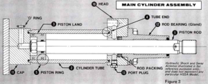
This technical bulletin has been designed to supplement previously published Bergen-Paterson Technical Maintenance Manuals for the Hydraulic Shock and Sway Arrestor (HSSA). When used in conjunction with the Technical Manual, the maintenance technician is afforded a tool by which he can make economic related proposals or decisions concerning repair or replacement of HSSA components. Damage to the individual components can be precluded during overhaul when the steps in the manual are properly followed. However, injury or deterioration of the parts during installation or while in service could detrimentally effect the performance of the Snubber if the same components are reassembled into the unit without proper repair or in some cases, replacement. The inspection guidelines that follow highlight prime areas of concern for the Snubber components. They will insure maximum functional operability and fluid containment integrity during future in-service use. Figures 1, 2 and 3 can be referenced as an aid in identifying hardware parts for both the Manifold and External Pipe configuration units. The following instruments should be used for final inspection and in particular when doubt persists in the technician’s mind as to a part’s acceptability.

  1. Flat Machinist’s Surface Plate.
  2. Surface Comparitor/Surface Profilometer.
  3. Dial Bore Gauges.
  4. Plug Gauges.

1 – PISTON ROD

After wiping the rod clean, inspect the chrome plated sur- face for paint, nicks or minor imperfections and/or chips. Surface imperfections can be found by using a surface profilometer or by running the edge of a thumb nail along the length of the rod and feeling for rough spots. The plated surface can be smoothed where necessary with crocus cloth. If any imperfections extend below the chrome plating, discard the part. The surface finish on rod should be maintained at 8-16 microinches.


A check should also be made for rod straightness. Rotate the piston between ‘V’ blocks and indicate the con- centricity with a .001″ indicator. The piston rod can also be rotated across a smooth and clean surface plate to inspect for straightness. A deformed rod is indicated by the following:


  1. Indicator readings in excess of .002″ per foot.
  2. Light (evidence of a gap) showing between the rod and plate surface.
  3. A slight flopping motion as the rod rolls. NOTE: The straightness of the rod must be maintained within .002″ per foot. Replace rods not meeting the straightness specification.

2 – CYLINDER TUBE

Inspect the inside wall and sealing surfaces for imper- fections as above. A sharp ended brass rod can be used to feel for imperfections deep within the tube. Imperfections can be removed using a flexible honing tool. Honing should not increase the tube I.D. by more than .005″ above the nominal diameter. This can be checked using a dial bore gauge. If pitting or nicks persist after honing, discard the part. The surface finish must be maintained between 10 and 20 microinches with a cross hatched pattern remaining on the bore after honing.

3 – PISTON LAND and 4- TUBE ENDS

Visually inspect the tube ends and ‘O’ Ting contact surfaces for nicks or rough spots. Smooth with crocus cloth. If imperfections persist discard the part. The surface finish should equal not exceed a maximum of 100 microinches in these areas.

5 – PISTON RINGS

Discard and replace any piston ring that is nicked or worn.

6 – RESERVOIR PISTON and 7 – RESERVOIR TUBE

Inspect for imperfections on tube contact surfaces. Smooth as required with crocus cloth without penetrating through the plated surfaces. Aluminum pistons may be cleaned up on stepped diameters below the largest outside diameter. The largest piston outside diameter should not be less than .010″ to .014″ below nominal size. The surface finish should equal 80 microinches max. If nicks or rough spots persist on the largest diameter, discard the part. Surface finishes on seal contact surfaces must not exceed 63 microinches.

8 – RESERVOIR BIAS SPRING and 9 – POPPET SPRINGS

Inspect for mechanical breakage or corrosion. If either is evident discard and replace the part.

10 – HEADS, 11 – CAPS, 12 – BEARINGS, 13 – PORT PLUGS, 14 – CONNECTOR TUBES, and Other Machined Components.

Inspect all sealing surfaces (ie surfaces contacting an ‘O’ ring or packings) for paint and surface imperfections. A light amount of crocus cloth wiping is acceptable. If nicks or scars persist, discard and replace the part. Surface fin- ishes should not exceed:

  1. 100 microinch max. on static sealing surfaces.
  2. 62 microinch max. on packing sealing surfaces.
  3. 32 microinch max. on bearing sliding surfaces.

15 – VALVE SEAT and 16 – POPPET

Wipe parts clean of all foreign materials. Inspect valve seats and conical surfaces of the poppets for scars or marks other than the coined bleed grooves. If any of these imperfections are evident, replace the part.


PISTON and ROD BEARING ALIGNMENT

Correct alignment can be checked by stroking the piston rod in a final assembled main cylinder prior to filling with fluid. The technician should be able to freely slide the piston rod back and forth by hand*. This check should be performed so that the technician may develop a “feel” for proper alignment and relative freedom of movement. Actual resistance tests are made on assembled units after they have been filled with hydraulic fluid. Failure of the unit to perform as such will indicate improper assembly of the components (provided each component has passed its individual inspection). Check for proper and even torquing of the tie rods and glands and retaining bolts. Also check for correct alignment between the rod bearing and those bearings that do not pilot into the cylinder head.

*This applies to Snubber bore sizes 1-1/2″ dia. thru 6″ dia. Larger bore sizes may require more than one technician to slide the piston rod.

Techbulletin images 2 1
Techbulletin images 2 2
Techbulletin images 2 3

Hydraulic Shock Functional Testing and Sway Arrestor and Performance Criteria

The Nuclear Regulatory Commission Inspection and Enforcement Bulletin No. 75-05 has become the primary document for Licensee action regarding Snubber testing. As stated in the document itself: “…the installation of Hydraulic Suppressors provides a system for the restraint of Category systems and components against excessive movement during seismic and fluid system transient conditions. Although in such a restraint system the failure or inoperability of a single Suppressor would not normally defeat the design function of the restraint system, it is desirable to provide for the periodic testing of a representative sample from the total population of Suppressors to assess the operational capability of the restraint system on a continuing basis.”


A requirement of the Bulletin was that the Licensee operating a power reactor facility, under NRC authorization:

  1. Review the design and installation of the hydraulic restraint systems.
  2. Review the design requirements which the various Suppressors are to meet and note the differences between the design and purchase requirements. Illustrations of the requirements are velocity, acceleration, load, release rate, etc.
  3. Describe the testing performed on the Hydraulic Suppressors by both the Licensee and Supplier prior to installation to assure their operation in accordance with the design specifications.
  4. Describe the surveillance programs including test procedures enforced by the Licensee or planned to be enforced for the operability of the Hydraulic Suppressors to meet the design specifications throughout the life of the facility.

As a result of the reports made to the NRC as requirement of Bulletin No. 75-05, and as additional information regarding Suppressor installation and performance became available the issuance of NRC Circulars such as Inspection and Enforcement Circular No. 75-05 and others contributed to the present functional test and inspection criteria now part of Licensee operating technical specifications. As an aid to the various Licensees operating with Bergen-Paterson Hydraulic Shock and Sway Arrestors, and Engineering review of Bulletin No. 75-05 was made and comments offered and published to the field. This Bulletin is a discussion of the Engineering Review.


Design requirements which the various suppressors are intended to meet should be taken from the architect-engineer job specifications. These would normally specify a piston rod velocity range during which rod lock-up actuation should take place. Regarding piston rod velocity during the bypass mode of operation, it is well to point out that the bypass system was originally incorporated into the control valve design simply as a means to insure reopening of the valve and unlocking of the restraint under any possible imposed operating condition. The concept of a piston rod velocity range during the bypass mode of operation was originally not a specific design requirement, but rather an operational characteristic that came out as a result during functional testing of the units. With the Bergen-Paterson units manufacturing control was placed on this velocity range as a means to achieve operational uniformity. The architect-engineer would be appraised of this bypass velocity rate in his review for product approval but, as was the case in many job specifications, it was not called for as a specific requirement.


The HSSA units are made available as standard catalog products in the following sizes:


HSSA SIZE CYLINDER BORE RATED CAPACITY
3 1.50″ 3,000 lbs.
10 2.50″ 10,000 lbs.
20 3.25″ 20,000 lbs.
30 4.00″ 30,000 lbs.
50 5.00″ 50,000 lbs.
70 6.00″ 70,000 lbs.
130 8.00″ 130,000 lbs.
200 10.00″ 200,000 lbs.


In application, the restraint designer establishes the “as installed” loading and movement conditions by for- mal calculation and normally makes his unit size and stroke selection based on the standard available unit having load and movement capabilities greater than his requirements, taking into account the necessary capacity reduction to account for column action of the overall strut length. As a plant operator, it must be assumed that the size selection made during the plant design phase has been reviewed and approved as being adequate for the calculated imposed loading conditions.


Each individual unit is tested to demonstrate fluid containment integrity and operational characteristics. It is necessary to describe both the design criteria and testing procedure with relation to a time frame because the manufacturing technique, testing apparatus, and procedures were changed when the manifold configuration model replaced the external pipe configuration model:


OPERATIONAL DESIGN CRITERIA

(Applies to all Bore Sizes)


  1. Piston shall be free to move in either direction with poppet valves remaining fully open for all piston velocities 10 inches per minute and slower. Tolerance plus or minus 2 inches per minute.1 (applies to all models).
  2. Poppet valves shall be designed for closure when piston velocity reaches 10 inches per minute for both compression and extension stroke. Tolerance on velocity for closure shall be plus or minus 2 inches per minute. (applies to all models).
  3. Orifice shall permit continued piston movement in either direction after valve closure at a rate of 4 to 6 inches per minute at rated design capacity.”


1 Tolerance on rates are established as a target goal to maintain uniformity of production. These values are arbitrary and have been selected as ultimate performance targets. The acceptance range is established by periodic review of individual test and phenomenon. results on all units in a production run and the range is mutually established and reduced as improved manufacturing techniques are employed. The acceptance range at time of manufacture becomes the functional test and performance acceptance criteria enforced by Bergen-Paterson Quality Control Personnel.


CURRENT TESTING CRITERIA

(Applicable to all units tested after October, 1972 Serial Numbers F84806 thru F98991, G12039 and up)

The assembly, final test requirement and operational characteristics for each individual unit is governed by specific procedures. Briefly described, the operational characteristics are established by physical test of each fully assembled unit. As part of the final assembly of the major components, the cylinder is set horizontally in a calibrated test stand. The cap end of the cylinder is bracketed to the test stand base and the piston rod is coupled in line to the piston rod of a power driven 8 inch bore hydraulic cylinder which is used to stroke the unit being tested. The velocity of the 8 inch bore unit can be varied by manually controlling the volume of fluid pumped for each direction of stroke. A force transducer and terminal display signal system is calibrated to: display force in pounds for both tension and compression and rod velocity is taken as a direct reading from a velocity instrument package integral to the test stand. The first check made is for piston rod alignment and binding. Prior to the cylinder being charged with fluid, the unit is stroked using an automatic “bind test” controlled drive setting on the test stand for the particular size unit being tested. Excessive resistance to movement would be indicated by the opening of a fluid pressure switch and the shutting down of the pump motor. Newer test equipment makes use of direct load instrumentation and reports resistance to movement or “drag” load directly in pounds force.

The cylinder is then charged during an extension stroke of the piston and the valve manifold attached and filled by a pouring operation. A temporary test fitting is attached to the valve and at least 4500 psi fluid pressure is applied for a minimum of 20 seconds during which fluid containment is visually checked.

The reservoir is then mounted and fluid filling is performed under pressure thru the normal field filling alemite fitting. The unit is now in its fully assembled and filled condition.

After random stroking of the unit, the poppet valve closure test is conducted for each direction of stroke by slowly increasing the piston velocity and noting the velocity at the time of an instantaneous increase in fluid pressure denoting valve closure “activation”.

The bypass “release” rate of flow in each direction is then checked by first applying a high velocity rate to close the valve and then establishing the rated force capacity of the unit. As the unit is stroked thru under the rated force condition, the velocity is checked and noted.

The unit is cleaned off and allowed to stand for a period of time on clean paper and then checked for evidence of leakage.


FORMER TESTING PROCEDURE

(Applicable to all units tested prior to October 1972)


Applies to all models except units made prior to June 1969. These can be identified as being units with external piping to the accumulator with the following serial numbers:

487278 thru 487820

and F60635 thru F81302

For these specific units, the bypass rate is approximately: 15 inches per minute for 2.50″ Bore Units 10 inches per minute for 3.25″ & 4.00″ Bore Units


The operational characteristics of the assembled unit is established by determining the control valve fluid flow characteristics at the various phases of operation. This is done by setting up each individual control valve in a fluid test stand and physically capturing and measuring the fluid flow volume over a specific time period and comparing the results to establish minimum- maximum flow rates at the test pressure that are equivalent to flow rates at actual design rated pressure. These values were originally determined by calculations and then by physical experiment using valves from units whose fully assembled characteristics had been established as being within the piston velocity tolerance ranges for the various phases of operation such as valve closure and bypass rates. The cylinder is filled with fluid prior to mounting of valve using a piston stroking operation and the valve is then mounted and filled using a pouring operation. The fluid containment integrity of the cylinders with valve body attached is established by applying 3500 psi fluid pressure thru the valve port to which the accumulator is normally attached and visually checking for leaks over a specific time period. The accumulator is then attached and charged with fluid, the unit is cleaned and allowed to stand for a period of time and then checked visually for leakage.

In addition to the above described testing procedures performed on each individual unit, dynamic testing has been performed on some selected units to demonstrate operational characteristics during shock loading and vibration conditions.

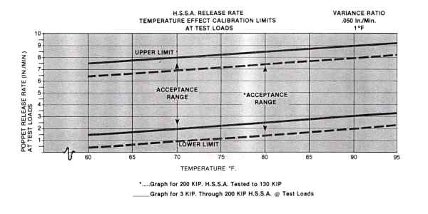
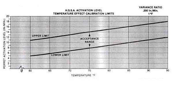
As a general consideration, it is well to point out that the piston rod velocity of 10 inches per minute was established as a standard by Bergen-Paterson in order to maintain uniformity. This value was selected as being greater than any normally anticipated thermal growth rate and less than any expected imposed shock loading. In reality, this condition should be considered as a velocity range and it is suggested that for normal piping installations, the accepted actuation velocity range should be approximately 5 to 20 inches per minute and approximately 2 to 20 inches per minute for bypass “release” rate at unit design load. These ranges are valid at an ambient temperature of 68-70°F. During review of test results it has been determined that the performance characteristics of the Hydraulic Shock and Sway Arrestor vary due to temperature considerations. As a result of temperature, variances have been


noted in viscosity and fluid density. Although it was always known that hydraulic units would be temperature sensitive, empirical analysis has shown that the effect is approximately .2 inches per minute of performance variance per “F., between the test range of 60° to 95 °F in activation and .05 ipm per °F for release rate. The temperature effect must be considered when performing functional tests to meet the NRC criteria. Failure to normalize the test results to the initial factory calibration criteria will result in erroneous failure analysis should a unit fall out of the acceptance range. Figures 1 and 2 illustrate the effect of temperature and its application to Bergen-Paterson’s manufacturing acceptance criteria.

Another consideration of functional testing is repeatability. As with any fluid device, repeatability of performance must be accounted for. The Hydraulic Shock and Sway Arrestor has demonstrated a functional repeat of activation and release rate calibration results within 2 3 inches per minute of normalized calibrated results. Repeatability is a function of:

  1. Fluid velocity and shock perturbations within the Hydraulic cylinder and flow control section.
  2. Load application technique.
  3. Terminal readout repeatability.
  4. Inertia of the test system, etc.


A testing technique should be developed to supplement the Licensee’s test procedure. This will insure uniformity of testing and an increased reliability in Snubber performance.
 

Techbulletin images 1

Techbulletin images 2

Ethylene-Propylene Elastomers Used in Hydraulic Shock and Sway Arrestors

The elastomer compounds selected for use in the Hydraulic Shock and Sway Arrestors are chosen to perform in nuclear power plant environments. The environments include:

  1. high temperature
  2. radiation
  3. steam and humidity in accordance with specifications


In addition, the seal must retain the working fluid of the Arrestor to enable it to be operational at any time.

To date there are no known elastomers that can meet the forty (40) year design life criteria specified by most users. However, the objective is to provide and adequate seal material that will provide the longest possible life and mini- mal maintenance.

To appreciate the difficulty of seal selection, it is necessary to understand the conditions which deteriorate the seal to a point where it is no longer considered functional. Both radiation and high temperature are the most detrimental of environmental conditions. Both are energy sources which work on the elastomer’s molecular structure eventually causing chain scission and modification of the mechanical properties. Of the Ethylene-Propylene family, compound E740-75 exhibits the best radiation resistance. Ethylene- Propylene as a generic material has excellent high temp- erature resistance and is usually applied in applications between -65°F and +300°F for continuous service. These temperature limits are general and must be considered in conjunction with the media the elastomer must seal.

A methyl phenyl polysiloxane silicone fluid (1154) is utilized as the working fluid in HSSA units. This material has been tested in high temperature and radiation environ- ments in conjunction with various EP seal compounds and has been found most compatible with the following:


E4248 A 75 (E740-75)
E4207 A 90 (E652-90)
E740-75
E93 B1 (E740-75)


These compounds are expressly used in static, dynamic, scraping and auxiliary sealing applications throughout the Hydraulic Arrestor. Compound E740-75 is generally requested in radiation environments but is in reality strictly an ‘O’ ring compound. Compound E4248 A 75 is the packing compound equivalent to E740-75. The manufacturing process involved in dynamic packing molding requires a modification of the ‘O’ ring compound to produce accept- able seals. E4248 A 75 does exhibit the same response to radiation, heat and fluid as it’s counterpart E740-75. In a similar manner, compound E4207 A 90 is equivalent to ‘O’ ring compound E652-90. However, this 90 durometer elas- tomer is not used in the fluid media of the Arrestor and is restricted to scraping or auxiliary sealing service. Compound E93 B1 is again equivalent to E740-75 and the seals molded from it are used in the quick fill (filler plug) fitting used on all HSSA unit pressurized reservoirs.

Another consideration is seal selection is durometer-Shore A hardness. The major portion of the life span of a snubber is spent in static service. For Hydraulic Snubbers this means low or no pressure to activate pressure responsive seals. Low durometers are selected to maintain an adequate pressure seal. In scraping or auxiliary sealing service, such as rod wipers and back up washers, high durometer materials are sought. These components are chosen to have a Shore A 90 durometer hardness, to safeguard against seal extru- sion and to wipe the piston rod clean of normal debris.

The useful shelf and service lives of the Ethylene-Propylene seal is a function of the storage and various environmental conditions. The average shelf life of the E-P seals furnished by Bergen-Paterson is expected to be between 5 and 10 years but are dependant upon the following:


  1. Ambient temperature not exceeding 120°F (49°C)
  2. Exclusion of air (oxygen)
  3. Exclusion of contamination
  4. Exclusion of light (particularly sunlight)
  5. Exclusion of ozone generating electrical devices
  6. Exclusion of radiation


Generally, polyethylene bags stored in larger cardboard containers or polyethylene lined craft paper bags insure optimal storage life.

The service life of the seal commences with installation and is again considered in the 5-10 year category but is depend- ant upon radiation and heat energy doses. The following figure illustrates radiation effects.


Compound E740-75 Radiation Test Data

Physical Properties Original 107Rads 108Rads
Hardness, Shore A; pts. (chg. pts.) 70 +3 +9
Tensil Strength, psi (chg. %) 2080 +3 -18
Elongation, % (chg. %) 233 -17 -18
Modulus @ 100%, psi (chg. %) 554 +46
TR-10,°F -59 -60
Compression Set, 25% Deflection 93 Days @RT
% of Original Deflection
6.7 28.6 90.5


All values are typical and should not be used for specification limits.


The radiation dosage limit for ‘O’ rings may be as high as 1 X 10⁸ Rads or as low as 1 X 10⁷ Rads for packings but 1 X 10⁷ Rads is expected to be the maximum normal accept- able radiation dosage. In terms of years, at normal plant design radiation levels, the service life approaches 10 years. In addition, temperature effects also determine service life. Operating below temperature limits of +200°F should pro- vide optimum life whereas exceeding that limit impairs service life. The other factor to be considered in service life is mechanical wear. Some application may dictate replace- ment of dynamic packings at earlier scheduled intervals than others due to wear alone.


Ethylene – Propylene materials are generally compatible with the following material:

  1. Phosphate-ester base hydraulic fluids
  2. Steam (to 400°F)
  3. Water/hot water
  4. Silicone oils and greases
  5. Dilute acids
  6. Dilute alkalies
  7. Ketones
  8. Alcohols


These materials are not compatible with:

  1. Petroleum oils
  2. Di-ester base lubricants


When in contact with these materials the Ethylene-Prop ylene compounds are severely degraded and/or destroyed due to excess swell, loss of mechanical properties or dis entegration.


Whenever a solvent is used to clean components of the Hydraulic Arrestor all traces (wetting) of the material should be removed prior to installation of new seals to assure that no contamination exists. There are numerous solvents available in the market and specific information regarding compatability of these with the Ethylene-Propylene seals may be obtained from the Product Engineering Department.


To summarize, the environment of the seal dictates its total life. In some cases 20 years may elapse from the time the seal was originally manufactured until it is retired from service. The 5 10 year storage and service lives, respectively, are projections based upon past history of similar elastomer compounds and service history of the Ethylene-Propylene seals themselves. The seal performance witnessed to date indicates that these projections are acceptable.

Blog

Galleries

Standards & Specifications

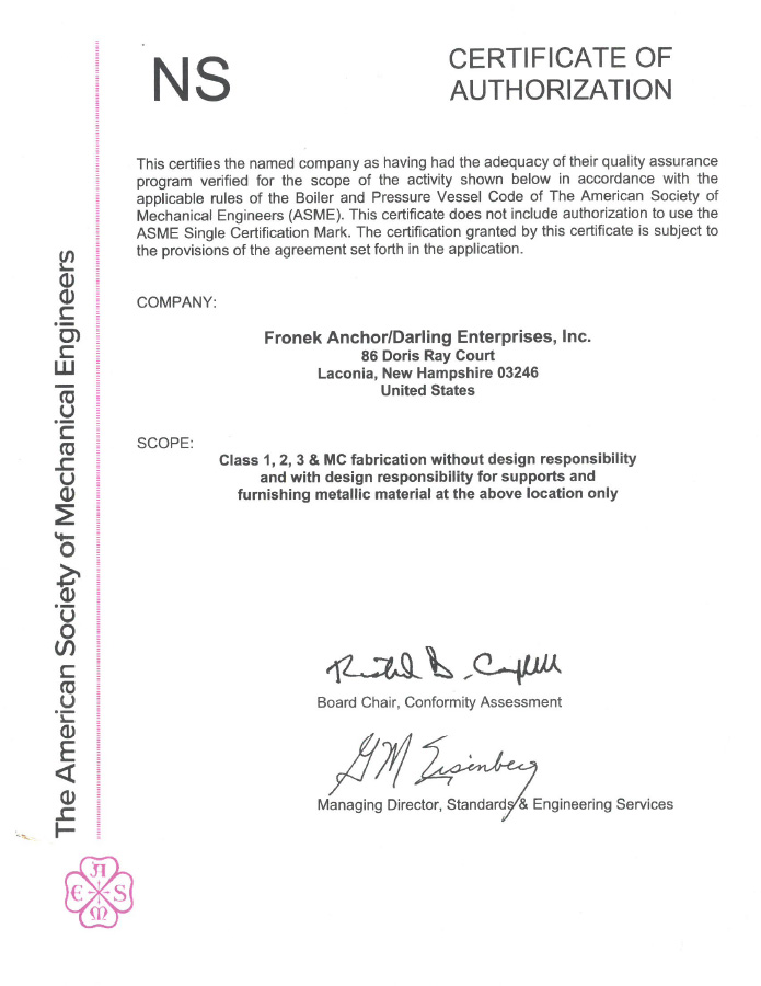
Fronek Anchor/Darling Enterprises holds an ‘NS’ Certificate of Accreditation issued by the American Society of Mechanical Engineers which enables them to manufacture component and pipe supports in accordance with the requirements of Section III of the Boiler and Pressure Vessel Code.  The scope of their Nuclear Supports Certification informs our Customers that they fabricate welded and non-welded Class 1, 2, 3 & MC supports with design responsibility and supply ferrous and nonferrous material for use in nuclear facilities worldwide.  Fronek Anchor/Darling Enterprises has been an ASME Certificate Holder since the early 1980’s.  Our Quality Program also meets the requirements of ASME NQA-1 (as mandated by NCA-4000), NCA-3800, 10CFR50 – Appendix B and ANSI/ASME N45.2.  Our standards of workmanship and level of quality assurance are well regarded throughout the nuclear power generation industry.
Certasme fronek

Webinars

Online Courses

Top