
Background
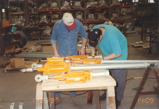
Snubber design support does not look the same at every stage of a project. An RFQ with almost no data attached, requires a different kind of engineering response before fabrication or a phone call in the middle of an outage-driven rebuild. The three cases below are drawn from actual customer engagements handled by Fronek Anchor/Darling Enterprises. Each one required application review, whether that was drawing markups, technical consultation, retrofit assistance, or custom configuration, at the point in the project where it was actually needed.
Problem
In all three engagements, the information available at the start of each request was insufficient to specify a correct snubber configuration. The first involved an alternate quote request built around a competitor’s part number with no load or displacement data attached. The second required confirming fit, hardware compatibility, and installation position before drawings went to the client, then catching a bracket count discrepancy when the markups came back. The third involved aging mechanical units that could not be rebuilt on the outage schedule, requiring a technically justified conversion to hydraulic replacements – sized from actual field conditions.
Case 1 – Alternate Quote: From a Part Number to a Specification
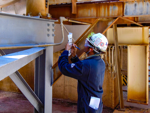
A distributor’s sales representative submitted a RFQ asking Fronek to quote an alternative to a competitor’s unit, identified only as “ASC C-201,” with a note that additional information could be provided on request.
The Challenge
An alternate quote is only as good as the engineering behind it. Without engineering details such as –
- The actual design load
- The expected thermal displacement at the installation point
Matching a competitor’s unit is guesswork. And guesswork on a snubber selection produces the same misfits at installation that a poorly considered original selection does. Fronek’s engineering team requested the load and displacement data before recommending a configuration.
How It Was Resolved
Using the confirmed design load of 14,700 lbs (approximately 15 Kips) and a net thermal displacement of 3.174 inches in the z-plane, Fronek recommended a Fig. 511AD 20 Kip x 6″ hydraulic snubber with one structural attachment and a pipe clamp.
And because the unit being replaced was a 10-inch-stroke Grinnell, the same 511AD built as a 20 Kip x 12″ was offered in case the client preferred the additional stroke for future flexibility and operating margin.
Both options were passed to the quotations team for lead time and pricing before being returned to the client.
Engineering Support Applied
- Application Review: Confirmed the actual design load and thermal displacement before recommending a configuration, rather than matching a catalog number to a competitor’s part.
- Custom Configuration: Two-stroke options were presented: the calculated minimum and an upsized alternative, based on the client’s operating margin preference.
Case 2 – Drawing Review: Catching a Bracket Count Before Fabrication
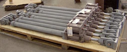
An approval drawing and client data sheets for a hydraulic snubber replacement job were forwarded internally from PT&P’s sales team to Fronek Anchor/Darling’s engineering team, requesting confirmation that a matching unit could be supplied before the drawings went out to the client for approval.
The Challenge
Two things had to be resolved before fabrication could begin:
First, whether Fronek’s standard hydraulic snubber would fit the available space and be able to function correctly in the client’s preferred hot/cold position.
Second, once the client’s markups came back, whether the assembly list and the drawing itself agreed on hardware requirements across all three units.
How It Was Resolved
Fronek confirmed that a 10 Kip x 6″ hydraulic snubber fits the allotted space.
As the unit’s pin size matched the existing Grinnell hardware, Fronek recommended the client leave the clamp and end brackets in place if they were not deteriorated, simplifying the replacement to the snubber body alone.
Fronek also asked whether the client required the unit to be positioned in the hot or cold position before drawings were finalized.
When the client’s markups came back, a review of the revised assembly sheet against the drawings identified a discrepancy on two of the three units. One unit showed an end bracket on the drawing that was not called out on the assembly list. A second unit showed two end brackets on the drawing, against a note for only one. Both discrepancies were flagged before the job was released to fabrication. The client confirmed that one end bracket was required across all three units, and the assembly sheet was corrected accordingly.
Engineering Support Applied
- Application Review: Confirmed stroke, fit, hot and cold installation position, and pin compatibility with existing field hardware before approving the design for the client’s review.
- Drawing Markups: Caught an end-bracket count discrepancy between the assembly list and the drawing on two of three units before fabrication began. Refer to The Snubber Terminology Guide for a detailed explanation of how pin-to-pin, preset, and attachment hardware interact in a snubber assembly.
Case 3 – Retrofit: Replacing Mechanical Units on an Outage Schedule
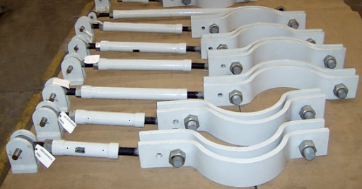
A utility’s piping SME requested an overhaul quote for four aging piping snubbers, a combination of 20 Kip hydraulic units and AD-1600L mechanical units, ahead of a scheduled spring outage, with a four-week turnaround targeted from removal to reinstallation.
The Challenge
Once the units arrived and were disassembled, one AD-1600L mechanical unit proved corroded well past the point of economical repair. The spare part needed to rebuild the second mechanical unit carried a 12-to 14-week lead time, well outside the outage window. A like-for-like rebuild was not going to happen on the client’s schedule, which meant Fronek’s
engineering team needed to propose and technically justify an alternative, then reflect it correctly in the drawings before the client’s installation crew and third-party engineering firm signed off.
How It Was Resolved
After a phone call to work through the client’s piping movement data, Fronek recommended replacing both mechanical units with equivalent hydraulic snubbers sized for actual field conditions. A cold pin-to-pin dimension of 75-1/4″, an expected movement of 5-1/2″, and an anticipated load of 6.0 Kips supported a 10 Kip hydraulic snubber with a 12″ stroke for each unit, built with a new structural attachment to replace the mounting hardware originally used by the mechanical struts.
The two hydraulic units that had been submitted separately for rebuild required only minor parts replacement and were completed on the original schedule. Once site measurements confirmed the true pin-to-pin dimensions, 73″ and 74,” against the preliminary drawing basis, Fronek issued corrected drawings with the piston rod set-point specified at +4 inches rather than mid-stroke, to accommodate approximately 6 inches of expected thermal displacement in the direction of pipe movement. The client’s maintenance department received an installation procedure ahead of the outage date.
Engineering Support Applied
- Retrofit Assistance: Assessed rebuild feasibility unit by unit and proposed hydraulic replacements once the mechanical snubbers were found impractical to rebuild on the outage schedule.
- Technical Consultation: Worked through the client’s actual piping movement data on a direct call to size the replacement, rather than defaulting to a like-for-like part swap.
- Custom Configuration: A new structural attachment was engineered to mate with the hydraulic replacement to the mounting hardware originally built for a mechanical unit.
- Drawing Markups: Pin-to-pin dimensions were corrected to site-measured values, and the preset was moved off mid-stroke to reflect the true thermal displacement in each direction.
For a broader look at what improper snubber selection costs when these steps are not taken, refer to The Real Cost of Improper Snubber Selection.
Summary
| Case | Support Provided | Outcome |
| Industrial Distributor | Application review translated a competitor’s part number into load- and displacement-based sizing, with two configuration options. | Alternate snubber recommendation and lead times were delivered ahead of the client’s quote deadline. |
| Mining Client | Application review confirmed fit and hardware compatibility; drawing markup caught an end-bracket mismatch on two of the three tagged units. | Corrected assembly sheet issued; job proceeded to paint and shipment on the original schedule. |
| Utility Client | Technical consultation and retrofit assistance replaced a non-repairable mechanical unit; drawing markups corrected pin-to-pin and set-point. | Hydraulic replacement engineered and drawings corrected; units shipped ahead of the scheduled outage. |
In each of these cases, the support Fronek provided was not a single deliverable. It was engineering judgment applied at whatever stage the project actually needed it, from a first RFQ with almost no data attached, to a markup review before fabrication, to a phone call in the middle of an outage-driven rebuild.
To discuss a specific snubber application, request a drawing review, or get engineering support on a retrofit, contact the Fronek Anchor/Darling team or request a quote.