
The Real Cost Of Improper Snubber Selection
Improper snubber selection is one of the most underappreciated sources of long-term cost in piping systems, in both commercial and industrial plants and nuclear facilities. The consequences are rarely visible at the time of installation. They develop over months or years and typically surface as a cracked weld, a degraded equipment nozzle, or an unplanned outage that costs significantly more than the correct device would have. This article covers five principal failure modes associated with incorrect snubber selection and the cost implications of each.
1. Structural Damage Risks
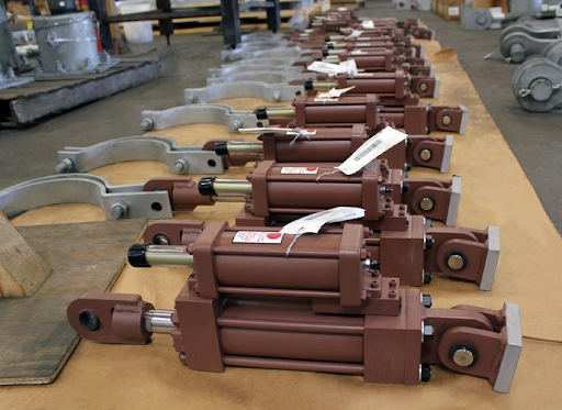
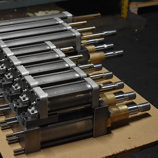
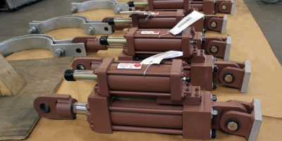
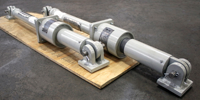
A hydraulic snubber is a velocity-sensitive device. It permits slow thermal movement to pass freely and locks up within milliseconds when the pipe accelerates dynamically. A mechanical snubber uses springs and pawl-and-ratchet mechanisms to achieve similar behavior. Selecting the wrong type or load rating results in a device that either fails to arrest the dynamic event or transmits forces that the structure was never designed to withstand.
Undersized Load Capacity
When the snubber’s rated capacity falls below the actual seismic or dynamic load, the device fails to arrest pipe motion during the event. The pipe displaces freely, transmitting shock loads into adjacent structures, hangers, and equipment connections. In nuclear applications, this failure mode can compromise the seismic qualification of the entire support design.
Note – An undersized snubber under dynamic load is an active failure point. The load that exceeds rated capacity transfers directly into the structure.
Oversized or Over-Constrained Installation
An oversized or poorly positioned snubber can produce equally damaging results. A snubber with excessive stiffness transfers loads into the piping system including attachment hardware, pins and lugs, which were not anticipated in the stress analysis. Pipe stress engineers account for snubber stiffness in their models. If the installed unit behaves differently than modeled, the entire stress calculation may be invalid.
2. Weld Cracking
Weld cracking is the failure mode most frequently observed in the field following improper snubber selection, and it typically takes time to manifest. Two primary mechanisms are involved: fatigue accumulation from repeated dynamic loading and constraint-induced stress from a snubber that binds during normal thermal cycling.
Fatigue from Dynamic Load Cycling
Piping systems in power generation and industrial plants go through a continuous cycle that includes startup, shutdown, load following, and pressure transients. When a snubber is improperly selected and repeatedly transmits higher-than-analyzed loads, the welded connections at pipe supports and structural attachments accumulate fatigue cycles faster. The pipe does not fail during a single event. It fails after thousands of cycles, with each one contributing incremental damage until a crack appears during maintenance inspection.
Thermal Binding and Constraint-Induced Stress
A snubber installed with insufficient stroke, incorrect preset position, or the wrong orientation will bind as the pipe thermally expands. Rather than moving freely through the slow thermal displacement, the snubber becomes a rigid restraint. The pipe then carries the thermal growth as a constrained stress concentrated at the nearest welds.
This condition is particularly damaging at small-bore branch connections and socket welds, where stress concentration factors are already heightened. If a snubber cannot move freely during normal thermal expansion, it behaves like a rigid support instead of allowing the pipe to expand and contract as designed.
3. Pipe Movement Issues
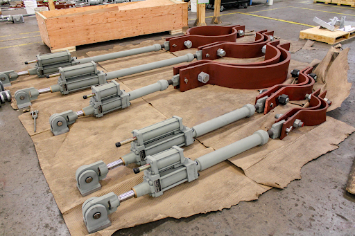
Thermal displacement and dynamic restraint represent fundamentally different design requirements. The snubber exists precisely because a single support cannot address both simultaneously. When this distinction is not reflected in the selection, or when the stroke is undersized, the consequences extend beyond the snubber itself.
Insufficient Stroke
A snubber preset at mid-stroke with 6 inches of total travel provides only 3 inches of movement in each direction. If the pipe grows 4 inches thermally, the snubber bottoms out before full displacement is reached, creating an unanalyzed restraint condition. Continued pipe movement against a bottomed-out snubber risks rod bending or mounting bracket fracture.
Stroke selection must be based on the actual thermal displacement at the installation point in the direction of the snubber’s axis. Lateral (side to side) displacement at a point where the snubber is oriented longitudinally (lengthwise) has no impact on stroke adequacy.
4. Mechanical vs. Hydraulic: Selecting the Right Device Type
| Parameters | Mechanical Snubbers | Hydraulic Snubbers |
| Operating Principle | Ratchet-based locking mechanism that responds to acceleration | Viscous dampers that respond proportionally to velocity |
| Suitable For | Low-frequency dynamic (seismic) events | Most power plant applications |
| Limitations | Not suited to sustain vibration environments, ratchet can engage unintentionally and accumulate constraint over time | Seals and Hydraulic fluid can degrade over time due to improper evaluation of the operating environment – thereby rendering reduces service life of the snubber. |
| Misapplication Risk | Unintended ratchet engagement and progressive constraint buildup in high-vibration environments | Failure to perform or active constraint of normal pipe movement if incorrect fluid is specified |
5. Long-Term Maintenance Costs
The purchase price of a snubber, including a nuclear-grade unit, represents a small fraction of the cost associated with an incorrect selection. Maintenance costs are where the full financial consequences of improper selection are realized.
Inspection and Surveillance Burden
Nuclear plants are required to perform functional testing on snubbers at defined intervals under 10CFR 50. A snubber that fails functional testing triggers an operability determination, an extent-of-condition review, and potentially accelerated testing of all similar devices. A single failed unit can initiate a fleet-wide evaluation. An incorrect device selection, particularly one that has been cycling under constraint or binding against thermal movement, increases failure rates and drives inspection costs disproportionately.
Unplanned Outage Costs
When a snubber failure or weld crack is discovered during operation, the plant must choose between continued operation under a degraded support condition and an unplanned outage to carry out repairs. For a nuclear unit, an unplanned outage at peak demand can cost $1M or more per day in replacement power. For a refinery, costs are comparable or higher. These figures represent the true cost of an incorrect snubber selection, not the cost of the device.
Repeat Failures and Root Cause Complexity
When a failed snubber is replaced with a device of the same incorrect specification, the failure will recur.Finding the real cause of the problem can be difficult because the effects often don’t appear until months or even years after the snubber was incorrectly selected.. By the time weld cracks are identified, the engineering basis for the original selection may no longer be available. Correcting the installation then requires a full re-analysis of the support design.
What Gets Triggered By A Wrong Selection
The table below summarizes the cost categories associated with each failure mode. Severity ratings reflect typical commercial and nuclear industrial experience.
| Failure Category | Primary Consequence | Cost Severity |
| Structural Damage | Unanalyzed restraint forces; bracket fracture; support failure under load | Critical |
| Weld Cracking | Fatigue accumulation; constraint-induced stress at branch connections | Critical |
| Pipe Movement | Snubber bottoming out; binding on thermal growth; loss of design basis | High |
| Maintenance Costs | Failed surveillance; unplanned outage; repeat root cause analysis | High |
Correct snubber selection requires load analysis, displacement data, geometry confirmation, and a thorough understanding of the dynamic environment at the installation point. Addressing these requirements during the engineering phase costs significantly less than correcting them after field consequences develop.
To discuss a specific snubber application, review an existing installation, or request an engineering evaluation, contact the Fronek Anchor/Darling team or request a quote today.