
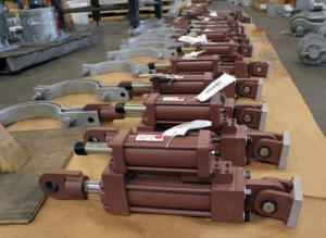
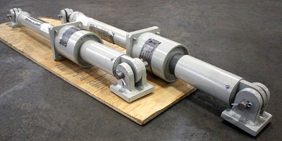
A snubber quotation, data sheet, or installation drawing contains its own specialized vocabulary. Engineers who work with these devices every day treat the terms as second nature. However, for maintenance planners, procurement teams, plant managers, and engineers new to piping support design, these terms are often overlooked or misunderstood, with real consequences in the field. This guide defines the terms that appear on every snubber data sheet, drawing, and purchase order, and explains how they interact in practice.
1. Core Dimensional Terminology
| Term | Definition |
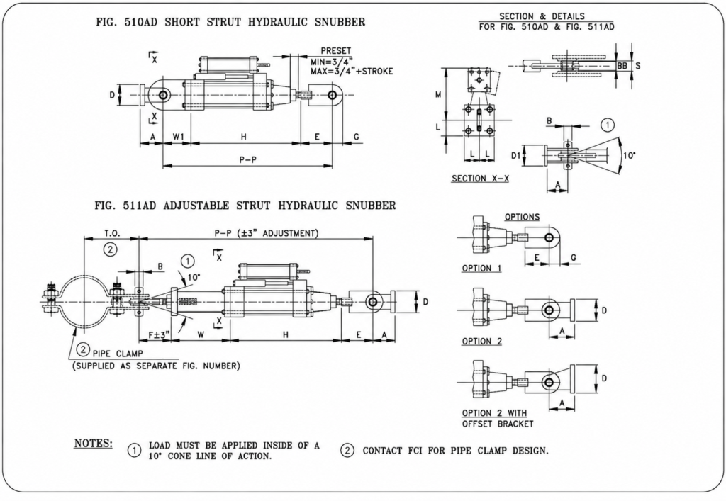
| Pin-to-Pin (PP) Length | The overall installed length of the snubber assembly is measured from the centerline of the structure-side pin to the centerline of the pipe-side pin. This is the governing dimension that determines whether the snubber fits the available space between the structural attachment and the pipe clamp. |
| Preset Position | The rod extension at which the snubber leaves the factory. Because the snubber must accommodate both cold (shutdown) and hot (operating) pipe positions, the rod is set to a specific point to ensure adequate stroke is available in both directions. Preset position is expressed either as an absolute rod extension measurement or as the resulting pin-to-pin length at the preset. |
| Cold Position | The physical position of the pipe, and therefore the snubber rod, is determined when the system is at normal shutdown temperature. This is typically the as-installed condition. The snubber is preset so that the cold position corresponds to the factory preset extension. |
| Hot Position | The physical position of the pipe when the system is at operating temperature. Thermal growth displaces the pipe from the cold position to the hot position. The snubber rod extends or retracts to follow this displacement. The difference between cold and hot positions, in the direction of the snubber axis, is the thermal displacement the snubber must accommodate without bottoming out. |
| Stroke | The total available travel of the snubber rod is measured from its fully retracted position to its fully extended position. The available stroke must be sufficient to ensure the snubber never bottoms out in either direction during thermal cycling. |
| Lock-Up Velocity | The rod velocity above which the snubber’s damping mechanism engages, and the device transitions from free movement to load-bearing restraint. For a hydraulic snubber, lock-up is a true velocity threshold; below it, the snubber follows thermal displacement freely; above it, the snubber arrests dynamic motion. Too high, and the snubber fails to engage during a seismic event; too low, and normal vibration or pressure transients cause unintended restraint. |
2. How These Terms Interact in Practice
Pin-to-Pin Drives the Installation
The structural attachment and the pipe clamp define a fixed envelope. The pin-to-pin length of the snubber assembly, including the rod, cylinder, clevis ends, and pins, must fit within that envelope at the cold-installed position. This is why pin-to-pin is the primary dimension on a data sheet, not cylinder bore or rod diameter.
Note – The cold position pin-to-pin dimension equals the sum of: cylinder body length + rod extension at preset + attachment hardware take-out at each end. If any element is estimated incorrectly, the snubber will not fit at the installation point.
Preset Enables Bidirectional Stroke
A snubber preset at its midpoint, 3 inches of extension on a 6-inch stroke device, has 3 inches of travel available in both directions. A snubber preset near its maximum extension has nearly all of its stroke available for retraction but almost none for extension. Preset must be calculated to leave adequate stroke in both the direction of thermal growth and the direction of thermal contraction.
Lock-Up Velocity Is Application-Specific
Fronek’s standard hydraulic snubbers are calibrated with a lock-up velocity in the range of approximately 8–12 inches per minute (IPM), which is appropriate for the vast majority of nuclear and industrial piping applications. Certain systems may require a different activation threshold based on operating conditions.
A geothermal plant experiencing slow thermal transients and seismic loading may require a different lock-up profile than a refinery steam line subjected to rapid pressure transients, water hammer, or high-frequency vibration. Where application-specific requirements exist, custom lock-up velocities can be engineered, calibrated, and tested to meet the design criteria.
3. Terms That Commonly Cause Field Problems
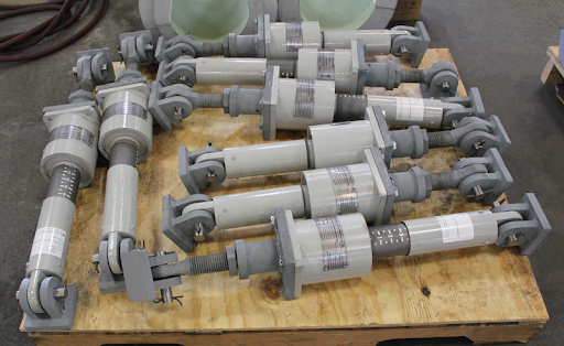
Three common misunderstandings account for the majority of snubber installation and specification errors encountered in the field:
Confusing pin-to-pin with cylinder length
A snubber quotation specifies pin-to-pin, not the cylinder body alone. The hardware take-out at each clevis end must be included. A customer who measures the cylinder and orders accordingly will receive a snubber that is too long by the total attachment take-out.
Ordering at the wrong preset
If the cold-position thermal displacement is not confirmed before ordering, the factory preset may leave insufficient stroke in one direction. The snubber may bind during thermal growth or bottom out, becoming an unintended fixed restraint at the limits of travel.
Misapplying lock-up velocity across device types
Mechanical snubbers engage based on acceleration, not velocity. They are not interchangeable with hydraulic snubbers in all environments, and their effective lock-up behavior differs. Specifying a mechanical unit in a sustained-vibration environment, or a hydraulic unit with the wrong silicone-based fluid for the temperature range, produces a device that fails to perform as designed.
Note – A snubber installed at the wrong preset, in the wrong orientation, or at the wrong pin-to-pin will fail silently until the pipe tells you something is wrong.
Summary
Understanding snubber terminology is essential to ensuring the device can be installed correctly, functions as designed, and allows the piping system to perform as intended under both thermal and dynamic loading. The table above provides a reference for the terms that appear most frequently in specifications, data sheets, and field installations.
For a more detailed look at what improper snubber selection costs in practice, read The Real Cost of Improper Snubber Selection.
To discuss a specific snubber specification, review an installation, or confirm pin-to-pin, preset, or stroke requirements, contact the Fronek Anchor/Darling team or request a quote.