This technical bulletin has been designed to supplement previously published Bergen-Paterson Technical Maintenance Manuals for the Hydraulic Shock and Sway Arrestor (HSSA). When used in conjunction with the Technical Manual, the maintenance technician is afforded a tool by which he can make economic related proposals or decisions concerning repair or replacement of HSSA components. Damage to the individual components can be precluded during overhaul when the steps in the manual are properly followed. However, injury or deterioration of the parts during installation or while in service could detrimentally effect the performance of the Snubber if the same components are reassembled into the unit without proper repair or in some cases, replacement. The inspection guidelines that follow highlight prime areas of concern for the Snubber components. They will insure maximum functional operability and fluid containment integrity during future in-service use. Figures 1, 2 and 3 can be referenced as an aid in identifying hardware parts for both the Manifold and External Pipe configuration units. The following instruments should be used for final inspection and in particular when doubt persists in the technician’s mind as to a part’s acceptability.
- Flat Machinist’s Surface Plate.
- Surface Comparitor/Surface Profilometer.
- Dial Bore Gauges.
- Plug Gauges.
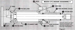
1 – PISTON ROD
After wiping the rod clean, inspect the chrome plated sur- face for paint, nicks or minor imperfections and/or chips. Surface imperfections can be found by using a surface profilometer or by running the edge of a thumb nail along the length of the rod and feeling for rough spots. The plated surface can be smoothed where necessary with crocus cloth. If any imperfections extend below the chrome plating, discard the part. The surface finish on rod should be maintained at 8-16 microinches.
A check should also be made for rod straightness. Rotate the piston between ‘V’ blocks and indicate the con- centricity with a .001″ indicator. The piston rod can also be rotated across a smooth and clean surface plate to inspect for straightness. A deformed rod is indicated by the following:
- Indicator readings in excess of .002″ per foot.
- Light (evidence of a gap) showing between the rod and plate surface.
- A slight flopping motion as the rod rolls. NOTE: The straightness of the rod must be maintained within .002″ per foot. Replace rods not meeting the straightness specification.
2 – CYLINDER TUBE
Inspect the inside wall and sealing surfaces for imper- fections as above. A sharp ended brass rod can be used to feel for imperfections deep within the tube. Imperfections can be removed using a flexible honing tool. Honing should not increase the tube I.D. by more than .005″ above the nominal diameter. This can be checked using a dial bore gauge. If pitting or nicks persist after honing, discard the part. The surface finish must be maintained between 10 and 20 microinches with a cross hatched pattern remaining on the bore after honing.
3 – PISTON LAND and 4- TUBE ENDS
Visually inspect the tube ends and ‘O’ Ting contact surfaces for nicks or rough spots. Smooth with crocus cloth. If imperfections persist discard the part. The surface finish should equal not exceed a maximum of 100 microinches in these areas.
5 – PISTON RINGS
Discard and replace any piston ring that is nicked or worn.
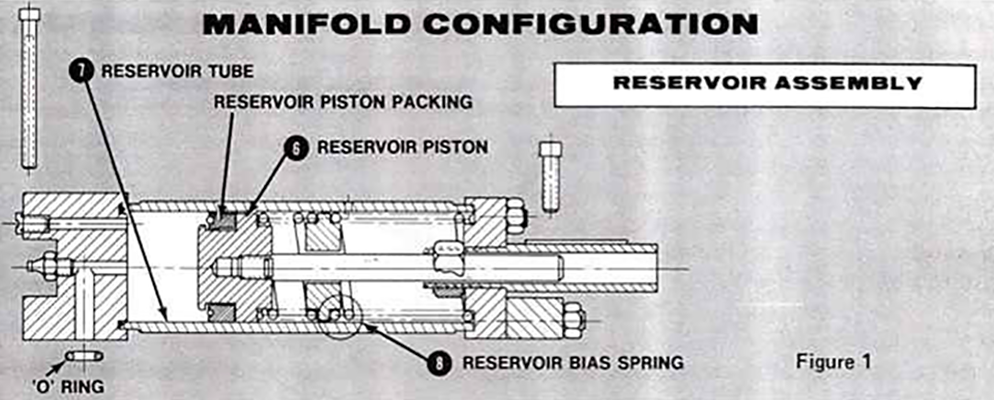
6 – RESERVOIR PISTON and 7 – RESERVOIR TUBE
Inspect for imperfections on tube contact surfaces. Smooth as required with crocus cloth without penetrating through the plated surfaces. Aluminum pistons may be cleaned up on stepped diameters below the largest outside diameter. The largest piston outside diameter should not be less than .010″ to .014″ below nominal size. The surface finish should equal 80 microinches max. If nicks or rough spots persist on the largest diameter, discard the part. Surface finishes on seal contact surfaces must not exceed 63 microinches.
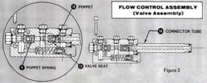
8 – RESERVOIR BIAS SPRING and 9 – POPPET SPRINGS
Inspect for mechanical breakage or corrosion. If either is evident discard and replace the part.
10 – HEADS, 11 – CAPS, 12 – BEARINGS, 13 – PORT PLUGS, 14 – CONNECTOR TUBES, and Other Machined Components.
Inspect all sealing surfaces (ie surfaces contacting an ‘O’ ring or packings) for paint and surface imperfections. A light amount of crocus cloth wiping is acceptable. If nicks or scars persist, discard and replace the part. Surface fin- ishes should not exceed:
- 100 microinch max. on static sealing surfaces.
- 62 microinch max. on packing sealing surfaces.
- 32 microinch max. on bearing sliding surfaces.
15 – VALVE SEAT and 16 – POPPET
Wipe parts clean of all foreign materials. Inspect valve seats and conical surfaces of the poppets for scars or marks other than the coined bleed grooves. If any of these imperfections are evident, replace the part.
PISTON and ROD BEARING ALIGNMENT
Correct alignment can be checked by stroking the piston rod in a final assembled main cylinder prior to filling with fluid. The technician should be able to freely slide the piston rod back and forth by hand*. This check should be performed so that the technician may develop a “feel” for proper alignment and relative freedom of movement. Actual resistance tests are made on assembled units after they have been filled with hydraulic fluid. Failure of the unit to perform as such will indicate improper assembly of the components (provided each component has passed its individual inspection). Check for proper and even torquing of the tie rods and glands and retaining bolts. Also check for correct alignment between the rod bearing and those bearings that do not pilot into the cylinder head.
*This applies to Snubber bore sizes 1-1/2″ dia. thru 6″ dia. Larger bore sizes may require more than one technician to slide the piston rod.