The Nuclear Regulatory Commission Inspection and Enforcement Bulletin No. 75-05 has become the primary document for Licensee action regarding Snubber testing. As stated in the document itself: “…the installation of Hydraulic Suppressors provides a system for the restraint of Category systems and components against excessive movement during seismic and fluid system transient conditions. Although in such a restraint system the failure or inoperability of a single Suppressor would not normally defeat the design function of the restraint system, it is desirable to provide for the periodic testing of a representative sample from the total population of Suppressors to assess the operational capability of the restraint system on a continuing basis.”
A requirement of the Bulletin was that the Licensee operating a power reactor facility, under NRC authorization:
- Review the design and installation of the hydraulic restraint systems.
- Review the design requirements which the various Suppressors are to meet and note the differences between the design and purchase requirements. Illustrations of the requirements are velocity, acceleration, load, release rate, etc.
- Describe the testing performed on the Hydraulic Suppressors by both the Licensee and Supplier prior to installation to assure their operation in accordance with the design specifications.
- Describe the surveillance programs including test procedures enforced by the Licensee or planned to be enforced for the operability of the Hydraulic Suppressors to meet the design specifications throughout the life of the facility.
As a result of the reports made to the NRC as requirement of Bulletin No. 75-05, and as additional information regarding Suppressor installation and performance became available the issuance of NRC Circulars such as Inspection and Enforcement Circular No. 75-05 and others contributed to the present functional test and inspection criteria now part of Licensee operating technical specifications. As an aid to the various Licensees operating with Bergen-Paterson Hydraulic Shock and Sway Arrestors, and Engineering review of Bulletin No. 75-05 was made and comments offered and published to the field. This Bulletin is a discussion of the Engineering Review.
Design requirements which the various suppressors are intended to meet should be taken from the architect-engineer job specifications. These would normally specify a piston rod velocity range during which rod lock-up actuation should take place. Regarding piston rod velocity during the bypass mode of operation, it is well to point out that the bypass system was originally incorporated into the control valve design simply as a means to insure reopening of the valve and unlocking of the restraint under any possible imposed operating condition. The concept of a piston rod velocity range during the bypass mode of operation was originally not a specific design requirement, but rather an operational characteristic that came out as a result during functional testing of the units. With the Bergen-Paterson units manufacturing control was placed on this velocity range as a means to achieve operational uniformity. The architect-engineer would be appraised of this bypass velocity rate in his review for product approval but, as was the case in many job specifications, it was not called for as a specific requirement.
The HSSA units are made available as standard catalog products in the following sizes:
| HSSA SIZE | CYLINDER BORE | RATED CAPACITY |
|---|---|---|
| 3 | 1.50″ | 3,000 lbs. |
| 10 | 2.50″ | 10,000 lbs. |
| 20 | 3.25″ | 20,000 lbs. |
| 30 | 4.00″ | 30,000 lbs. |
| 50 | 5.00″ | 50,000 lbs. |
| 70 | 6.00″ | 70,000 lbs. |
| 130 | 8.00″ | 130,000 lbs. |
| 200 | 10.00″ | 200,000 lbs. |
In application, the restraint designer establishes the “as installed” loading and movement conditions by for- mal calculation and normally makes his unit size and stroke selection based on the standard available unit having load and movement capabilities greater than his requirements, taking into account the necessary capacity reduction to account for column action of the overall strut length. As a plant operator, it must be assumed that the size selection made during the plant design phase has been reviewed and approved as being adequate for the calculated imposed loading conditions.
Each individual unit is tested to demonstrate fluid containment integrity and operational characteristics. It is necessary to describe both the design criteria and testing procedure with relation to a time frame because the manufacturing technique, testing apparatus, and procedures were changed when the manifold configuration model replaced the external pipe configuration model:
OPERATIONAL DESIGN CRITERIA
(Applies to all Bore Sizes)
- Piston shall be free to move in either direction with poppet valves remaining fully open for all piston velocities 10 inches per minute and slower. Tolerance plus or minus 2 inches per minute.1 (applies to all models).
- Poppet valves shall be designed for closure when piston velocity reaches 10 inches per minute for both compression and extension stroke. Tolerance on velocity for closure shall be plus or minus 2 inches per minute. (applies to all models).
- Orifice shall permit continued piston movement in either direction after valve closure at a rate of 4 to 6 inches per minute at rated design capacity.”
1 Tolerance on rates are established as a target goal to maintain uniformity of production. These values are arbitrary and have been selected as ultimate performance targets. The acceptance range is established by periodic review of individual test and phenomenon. results on all units in a production run and the range is mutually established and reduced as improved manufacturing techniques are employed. The acceptance range at time of manufacture becomes the functional test and performance acceptance criteria enforced by Bergen-Paterson Quality Control Personnel.
CURRENT TESTING CRITERIA
(Applicable to all units tested after October, 1972 Serial Numbers F84806 thru F98991, G12039 and up)
The assembly, final test requirement and operational characteristics for each individual unit is governed by specific procedures. Briefly described, the operational characteristics are established by physical test of each fully assembled unit. As part of the final assembly of the major components, the cylinder is set horizontally in a calibrated test stand. The cap end of the cylinder is bracketed to the test stand base and the piston rod is coupled in line to the piston rod of a power driven 8 inch bore hydraulic cylinder which is used to stroke the unit being tested. The velocity of the 8 inch bore unit can be varied by manually controlling the volume of fluid pumped for each direction of stroke. A force transducer and terminal display signal system is calibrated to: display force in pounds for both tension and compression and rod velocity is taken as a direct reading from a velocity instrument package integral to the test stand. The first check made is for piston rod alignment and binding. Prior to the cylinder being charged with fluid, the unit is stroked using an automatic “bind test” controlled drive setting on the test stand for the particular size unit being tested. Excessive resistance to movement would be indicated by the opening of a fluid pressure switch and the shutting down of the pump motor. Newer test equipment makes use of direct load instrumentation and reports resistance to movement or “drag” load directly in pounds force.
The cylinder is then charged during an extension stroke of the piston and the valve manifold attached and filled by a pouring operation. A temporary test fitting is attached to the valve and at least 4500 psi fluid pressure is applied for a minimum of 20 seconds during which fluid containment is visually checked.
The reservoir is then mounted and fluid filling is performed under pressure thru the normal field filling alemite fitting. The unit is now in its fully assembled and filled condition.
After random stroking of the unit, the poppet valve closure test is conducted for each direction of stroke by slowly increasing the piston velocity and noting the velocity at the time of an instantaneous increase in fluid pressure denoting valve closure “activation”.
The bypass “release” rate of flow in each direction is then checked by first applying a high velocity rate to close the valve and then establishing the rated force capacity of the unit. As the unit is stroked thru under the rated force condition, the velocity is checked and noted.
The unit is cleaned off and allowed to stand for a period of time on clean paper and then checked for evidence of leakage.
FORMER TESTING PROCEDURE
(Applicable to all units tested prior to October 1972)
Applies to all models except units made prior to June 1969. These can be identified as being units with external piping to the accumulator with the following serial numbers:
487278 thru 487820
and F60635 thru F81302
For these specific units, the bypass rate is approximately: 15 inches per minute for 2.50″ Bore Units 10 inches per minute for 3.25″ & 4.00″ Bore Units
The operational characteristics of the assembled unit is established by determining the control valve fluid flow characteristics at the various phases of operation. This is done by setting up each individual control valve in a fluid test stand and physically capturing and measuring the fluid flow volume over a specific time period and comparing the results to establish minimum- maximum flow rates at the test pressure that are equivalent to flow rates at actual design rated pressure. These values were originally determined by calculations and then by physical experiment using valves from units whose fully assembled characteristics had been established as being within the piston velocity tolerance ranges for the various phases of operation such as valve closure and bypass rates. The cylinder is filled with fluid prior to mounting of valve using a piston stroking operation and the valve is then mounted and filled using a pouring operation. The fluid containment integrity of the cylinders with valve body attached is established by applying 3500 psi fluid pressure thru the valve port to which the accumulator is normally attached and visually checking for leaks over a specific time period. The accumulator is then attached and charged with fluid, the unit is cleaned and allowed to stand for a period of time and then checked visually for leakage.
In addition to the above described testing procedures performed on each individual unit, dynamic testing has been performed on some selected units to demonstrate operational characteristics during shock loading and vibration conditions.
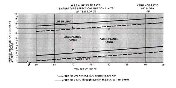
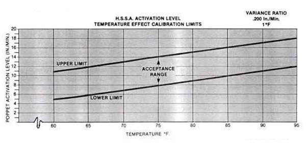
As a general consideration, it is well to point out that the piston rod velocity of 10 inches per minute was established as a standard by Bergen-Paterson in order to maintain uniformity. This value was selected as being greater than any normally anticipated thermal growth rate and less than any expected imposed shock loading. In reality, this condition should be considered as a velocity range and it is suggested that for normal piping installations, the accepted actuation velocity range should be approximately 5 to 20 inches per minute and approximately 2 to 20 inches per minute for bypass “release” rate at unit design load. These ranges are valid at an ambient temperature of 68-70°F. During review of test results it has been determined that the performance characteristics of the Hydraulic Shock and Sway Arrestor vary due to temperature considerations. As a result of temperature, variances have been
noted in viscosity and fluid density. Although it was always known that hydraulic units would be temperature sensitive, empirical analysis has shown that the effect is approximately .2 inches per minute of performance variance per “F., between the test range of 60° to 95 °F in activation and .05 ipm per °F for release rate. The temperature effect must be considered when performing functional tests to meet the NRC criteria. Failure to normalize the test results to the initial factory calibration criteria will result in erroneous failure analysis should a unit fall out of the acceptance range. Figures 1 and 2 illustrate the effect of temperature and its application to Bergen-Paterson’s manufacturing acceptance criteria.
Another consideration of functional testing is repeatability. As with any fluid device, repeatability of performance must be accounted for. The Hydraulic Shock and Sway Arrestor has demonstrated a functional repeat of activation and release rate calibration results within 2 3 inches per minute of normalized calibrated results. Repeatability is a function of:
- Fluid velocity and shock perturbations within the Hydraulic cylinder and flow control section.
- Load application technique.
- Terminal readout repeatability.
- Inertia of the test system, etc.
A testing technique should be developed to supplement the Licensee’s test procedure. This will insure uniformity of testing and an increased reliability in Snubber performance.