
Nuclear plants operating in the United States are subject to Title 10, Code of Federal Regulations, Part 50, referred to as 10CFR50. For snubbers, this regulation defines the quality assurance and testing framework governing how snubbers are manufactured, installed, tested, and maintained throughout the operating life of the plant.
What 10CFR50 Covers for Snubbers
10CFR50 is the primary federal regulation governing the domestic licensing of nuclear power plants, administered by the Nuclear Regulatory Commission(NRC). Two provisions apply directly to snubbers.
10CFR50 Appendix B establishes the Quality Assurance Criteria for Nuclear Power Plants. It defines the requirements governing how safety-related components are designed, fabricated, inspected, tested, and documented. Any hydraulic or mechanical snubber installed in a safety-related application must be manufactured under a quality program that meets these requirements.
Fronek Anchor/Darling’s quality program meets the requirements of 10CFR50 Appendix B, along with:
- ASME NQA-1 (as mandated by Nuclear Components and Assemblies -4000)
- NCA-3800
- ANSI/ASME N45.2
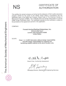
Fronek has held an ASME NS Certificate of Accreditation since the early 1980s, enabling the manufacture of component and pipe supports in accordance with Section III of the ASME Boiler and Pressure Vessel Code. The scope covers welded and non-welded Class 1, 2, 3, and MC supports with design responsibility for nuclear facilities worldwide.
NRC Bulletin 75-05: The Regulatory Basis for Snubber Functional Testing
The functional testing requirements for snubbers at nuclear plants trace directly to NRC Inspection and Enforcement Bulletin No. 75-05. As documented in Fronek’s functional testing technical bulletin, Bulletin 75-05 became the primary document for licensee action on snubber testing.
The bulletin established that while the failure of a single suppressor would not normally defeat the design function of the restraint system, periodic testing of a representative sample from the total population is necessary to assess operational capability on a continuing basis.
As a requirement of the bulletin, each licensee operating a power reactor facility under NRC authorization was required to:
- Review the design and installation of the hydraulic restraint systems
- Review the design requirements each suppressor is intended to meet, including velocity, acceleration, load, and release rate
- Describe testing performed on hydraulic suppressors by both the licensee and supplier prior to installation
- Describe surveillance programs and test procedures enforced or planned to be enforced for operability throughout the facility’s life
The reports submitted in response to Bulletin 75-05, combined with additional performance data, contributed to the NRC circulars and ultimately to the functional test and inspection criteria now part of licensee operating technical specifications.
Operational Design Criteria: What the Functional Test Confirms
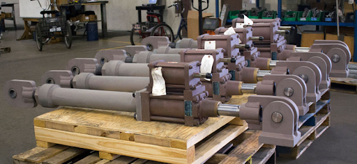
Every Fronek hydraulic snubber is individually tested before shipment against three operational design criteria that apply to all bore sizes:
| Criterion | Requirement |
| Free movement | Piston moves freely in either direction with poppet valves fully open at all velocities at or below 10 inches per minute. Tolerance: plus or minus 2 inches per minute. |
| Lock-up | Poppet valves close when piston velocity reaches 10 inches per minute in both compression and extension strokes. Tolerance: plus or minus 2 inches per minute. |
| Bypass release rate | After valve closure, the orifice permits continued piston movement in either direction at 4 to 6 inches per minute at rated design capacity. |
These three parameters are what every functional test is designed to confirm. A unit that fails any one of these criteria requires an operability determination and may trigger an extent-of-condition review covering similar units across the plant.
HSSA Size and Rated Capacity Reference
The hydraulic shock and sway arrestor units are available in the following standard catalog sizes. Load rating and bore size are the primary selection parameters for a given installation:
| HSSA Size | Cylinder Bore | Rated Capacity |
| 3 | 1.50 in | 3,000 lbs |
| 10 | 2.50 in | 10,000 lbs |
| 20 | 3.25 in | 20,000 lbs |
| 30 | 4.00 in | 30,000 lbs |
| 50 | 5.00 in | 50,000 lbs |
| 70 | 6.00 in | 70,000 lbs |
| 130 | 8.00 in | 130,000 lbs |
| 200 | 10.00 in | 200,000 lbs |
The restraint designer establishes the as-installed loading and movement conditions by formal calculation and selects the standard unit with load and movement capabilities greater than the calculated requirements, accounting for capacity reduction due to column action of the overall strut length.
How Fronek Tests Each Unit Before It Ships
The factory testing procedure, documented in Fronek’s functional testing technical bulletin, confirms all three criteria above before a unit leaves the facility:
- The cylinder is placed horizontally in a calibrated test stand with a force transducer and velocity instrumentation package
- A bind test is run before fluid charging to confirm piston rod alignment and freedom of movement
- The cylinder is charged with fluid and a minimum pressure of 4,500 psi is applied for at least 20 seconds while fluid containment is visually checked
- The poppet valve closure test is run in each direction of stroke by incrementally increasing piston velocity until valve activation is confirmed
- The bypass release rate is checked in each direction under rated force conditions
- The unit stands on clean paper after testing for a final visual leakage check
This sequence is applied to every unit individually, not on a sampling basis.
Why Temperature Normalization Is Required During Field Testing
The performance characteristics of a hydraulic shock and sway arrestor vary with temperature due to changes in fluid viscosity and density. As confirmed in Fronek’s functional testing technical bulletin, empirical analysis has established the following:
- Activation velocity varies by approximately 0.2 inches per minute per degree Fahrenheit across a test range of 60 to 95 degrees Fahrenheit
- Bypass release rate varies by approximately 0.05 inches per minute per degree Fahrenheit across the same range
A unit tested at a field temperature significantly different from the factory calibration temperature will produce results that appear to fall outside the acceptance range even when the unit is performing correctly. Failure to normalize test results to the initial factory calibration criteria produces incorrect failure analysis. This is a documented source of erroneous functional test failures in the field.
Replacement Parts and Code of Service Ordering
For nuclear plants ordering replacement parts or replacement cylinders for safety-related snubbers, the code of service designation on the purchase order determines the quality requirements the part must meet. Fronek’s replacement parts ordering requirements specify that each order must include one of the following designations:
- ASME Section III
- 10CFR50 Appendix B
- ANSI N45.2
- Commercial grade
Ordering a safety-related replacement part under a commercial grade designation, or omitting the code of service entirely, means the part will not be manufactured to the documentation and traceability requirements that 10CFR50 Appendix B demands. This is one of the most common ordering errors on replacement parts for aging nuclear snubber populations and one of the most straightforward to prevent. For plants reviewing their legacy snubber populations, the considerations involved are covered in detail in Why Old Nuclear Plants Are Replacing Aging Piping Snubbers.
Summary
10CFR50 Appendix B governs the quality assurance requirements for every safety-related snubber manufactured for a nuclear plant. NRC Bulletin 75-05 established the functional testing framework licensees are required to implement. The three operational design criteria, free movement below 10 inches per minute, lock-up at 10 inches per minute, and a bypass release rate of 4 to 6 inches per minute at rated capacity, are what every functional test confirms. Temperature normalization of test results is required for accurate pass/fail determination. Correct code of service designation on replacement parts orders ensures a replacement component meets the same quality standard as the original.
For questions on snubber quality requirements, functional test criteria, or replacement parts ordering under 10CFR50 Appendix B, schedule a meeting with Fronek’s engineering team, contact us, or request a quote.